Hello, welcome to visit Changzhou Hengtuo Electronic Weighing Apparatus Co., Ltd. official website!
| CH

Sources: | Date: 2016-02-27 14:33:23 | Browse:201187
In the current science and technology industry, the use of load cells is ubiquitous, because the load cell itself is a sturdy, durable, and reliable electromechanical product, but in order to ensure the measurement accuracy, there are still many probl…
In the current science and technology industry, the use of load cells is ubiquitous, because the load cell itself is a sturdy, durable, and reliable electromechanical product, but in order to ensure the measurement accuracy, there are still many problems that should be paid attention to in use. So what problems should be paid attention to when using load cells? The following describes some problems that must be paid attention to when using load cells:
1. Electrical connection (such as the signal cable of the sensor, should not be arranged in parallel with the strong power line or control line (for example, do not put the sensor signal line, the strong current power line and the control line in the same pipe). If they must be parallel Place, then the distance between them should be kept above 50CM, and the signal line should be covered with a metal tube.
2. Try to set up some "baffles" around the load cell, and even cover the sensor with a thin metal plate. This can prevent sundries from contaminating the sensor and certain movable parts, and this "contamination" often makes the movable parts uncomfortable and affects weighing accuracy. Whether the system is uncomfortable with exercise can be judged by the following methods. That is, add or subtract about one-thousandth of the rated load on the weighing platform to see if the weighing indicator has a reaction. If there is a reaction, it means that the movable part is not "contaminated".
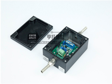
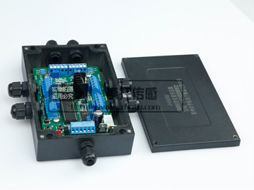
3. All wires leading to or from the display circuit should be shielded cables. The connection and grounding point of the shielded wire should be reasonable. If it is not grounded through the mechanical frame, it is grounded externally, but the shielded wires are not grounded after being connected to each other and are floating. Note: There are 3 sensors that are connected in parallel. The sensor itself is 4-wire, but it is changed to 6-wire connection in the junction box. The sensor output signal readout circuit should not be placed in the same box with the thyristor, contactor, etc. that can cause strong interference, and the equipment with considerable heat generation. If this cannot be guaranteed, it should be considered between them Set a baffle to isolate it, and install a fan in the box. The electronic circuit used to measure the output signal of the sensor should be equipped with an independent power supply transformer as much as possible, rather than sharing the same main power supply with equipment such as contactors.
4. Try to use structural accessories with automatic positioning (reset) function, such as spherical bearings, joint bearings, positioning fasteners, etc. They can prevent certain lateral forces from acting on the sensor. It should be noted that some lateral forces are not caused by mechanical installation, such as lateral force caused by thermal expansion, lateral force caused by wind, and lateral force caused by the vibration of agitator on certain container weighing instruments, which are not caused by mechanical installation. . Some weighing instruments must be connected to the accessories on the scale body (such as the conveying pipe of the container scale, etc.). We should make them as soft as possible in the direction of the load axis of the sensor to prevent them from "eating" the true load of the sensor The combination causes errors.
5. Level adjustment: There are two aspects to level adjustment. One is that the mounting plane of a single sensor mounting base should be leveled with a level gauge. On the other hand, the mounting surface of the mounting base of multiple sensors should be adjusted to one level as much as possible (using a level), especially if the number of sensors is more than three. In the weighing system, this point should be paid more attention to. The main purpose of doing so is to make the load of each sensor basically the same. The loading direction of each load cell is determined, and when we use it, we must load the load in this direction. Lateral forces, additional bending moments, and torque forces should be avoided as much as possible.
6. Sensors should use hinged copper wires (cross-sectional area of about 50mm2) to form electrical bypasses to protect them from welding current or lightning strikes. During the use of the sensor, strong thermal radiation must be avoided, especially one-sided strong thermal radiation.
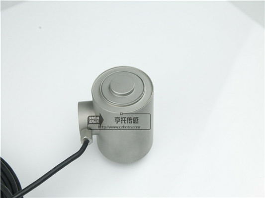
7. Handle with care, especially the small-capacity sensor made of aluminum alloy elastomer. Any impact or drop may cause great damage to its measurement performance. For a large-capacity load cell, generally speaking, it has a relatively large self-weight, so it is required to use appropriate lifting equipment (such as chain hoists, electric hoists, etc.) when handling and installing. The mounting surface of the base where the sensor is installed should be flat and clean, without any oil film, glue film, etc. The mounting base itself should have sufficient strength and rigidity, which is generally required to be higher than the strength and rigidity of the sensor itself.
8. Although the load cell has a certain overload capacity, the load cell should be prevented from being overloaded during the installation of the weighing system. It should be noted that even a short-term overload may cause damage to the sensor ^. In the installation process, if it is really necessary, you can replace the sensor with a block of the same height as the sensor, and then replace the sensor after ^. In normal operation, the sensor should generally be equipped with mechanical structural parts for overload protection. If a screw is used to fix the sensor, a certain tightening torque is required, and the screw should have a certain screw depth. Generally speaking, the fixed screw uses a high-strength screw.
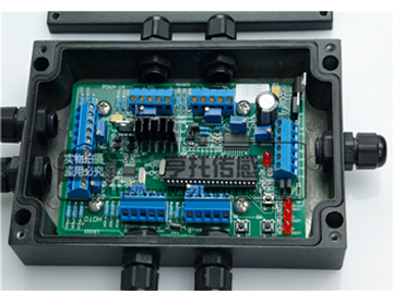
9. In any case, the power line and control line should be twisted together at a degree of 50 revolutions per meter. If the sensor signal line needs to be extended, a special sealed cable junction box should be used. If this kind of junction box is not used, but the cable and the cable are directly connected (soldering end), special attention should be paid to the sealing and moisture-proofing. After the connection, the insulation resistance should be checked and the standard (2000~5000M) should be met. If necessary, The sensor should be recalibrated. If the signal cable is very long and high measurement accuracy is required, a cable compensation circuit with a relay amplifier should be considered.
Strictly follow the above operation and use, the measurement results obtained when the load cell is used will be more ^, more convenient, and the load cell will not be easily damaged, and the life and maintenance can be better.
A few days ago, Tesla CEO Elon Musk bombarded the technical limitations of lidar as a sensor for self-driving cars on the company’s self-dri…
The weighing module industry market survey report is to use scientific methods to purposefully and systematically collect, record and organiz…
In the current technology industry, a variety of electronic systems and mechanical systems will use various weighing devices, and the most im…
At present, and even in the next few decades, sensors are listed as the top 10 technology products that affect and change the world economy a…
At present, load cells have already penetrated into a wide range of fields such as industrial production, space development, ocean exploratio…
In the combined strain pressure sensor, elastic sensitive elements can be divided into sensing elements and elastic strain elements. The sens…